Hacking Rotary Dials
by yeat
Once upon a time, telephones were not omnipresent and not mobile at all.
A typical phone consisted of a massive body connected to both a receiver and a wall socket via cables. Especially in the early days of telephony, those devices were wall-mounted and not intended to be carried around. Oh, and you couldn't use them to take photos, text your friends, manage your calendar or look up stock prices or something in your favorite encyclopedia. You just made calls (and you were supposed to keep them short).
Fortunately, those days are long gone and you're probably even reading this article on your mobile phone. But unlike modern smartphones which nowadays come with built-in obsolescence, phones of the early days were extremely durable, worked for decades, and may even be working today!
Though maybe perceived as clumsy, heavy, and cumbersome by today's standards, some technological details are still quite fascinating.
This article deals with one of those details: the rotary dial, whose appearance and characteristic sound is still widely associated with telephony in the "good old days."
First, I will share my journey to understanding how it works and then I'll describe how it can be utilized today.
Curtain Up for the Rotary Dial!
After introducing the first commercial telephone networks in the late 19th century, it took more than a decade to invent a feasible way of connecting two parties without involving the assistance of a human operator. As it was state-of-the-art back then, the problem was solved using a complex mixture of mechanics and electronics.
Telephones equipped with rotary dials, together with automated switching, brought a tremendous improvement of communication technology in the very early 20th century. Thanks to this invention, connections between callers no longer had to be initiated manually (though complete conversion to automated switching took many decades to come - especially in remote areas).
The decline of rotary dial phones started in the 1960s - that's no earlier than half a century after its introduction. At first, they were superseded by push-button pulse phones which were merely mimicking the pulses of a rotary dial whenever one of their buttons was pushed. Not much later, those were replaced by Touch-Tone phones, emitting the typical two-frequency sounds we still associate with dialing phone numbers. In the 1980s, rotary dial phones had mostly disappeared (at least throughout the western hemisphere).
Even today, such old telephones can be used if connected, for instance, to an analog port of a DSL router. Most probably, receiving of calls would work without further effort. Only for outgoing calls, a pulse-to-DTMF converter may be required as most modern routers don't recognize dial pulses anymore.
As they were manufactured in batches of millions, rotary dial phones, as well as spare rotary dials, can easily be obtained at the online auction post of your choice.
So why not have some fun with it?
A Closer Look
I was lucky enough to get my hands on an old dial from the 1950s.
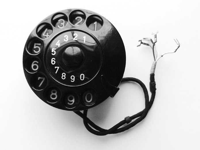
Back then, the mechanism was not encapsulated, so one can easily watch what's happening when turning the dial. Here's what I observed:
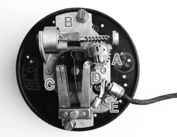
The dial on the front is attached to the large gear in the center on the rear side.
This gear spins a rotor [A] which is adjusted to constant speed by a tiny centrifugal brake [B].
The center gear also toggles two switches at [C] - initially one is open and one is closed.
There is an additional switch at [D] which is normally closed and opened in pulses by the spinning rotor [A].
Last but not least, there is a cable attached at [E], forming the connection to the outside world. Its four wires were the focus of my further investigations.
To Switch or Not to Switch
As the electrical part of the mechanism is composed of several switches, I assumed that the four wires simply constituted the terminals of on/off switches.
Using a continuity tester, I discovered that two wires were interconnected (current flows, i.e., switch closed) while the other two were not (no current flows, i.e., switch open).
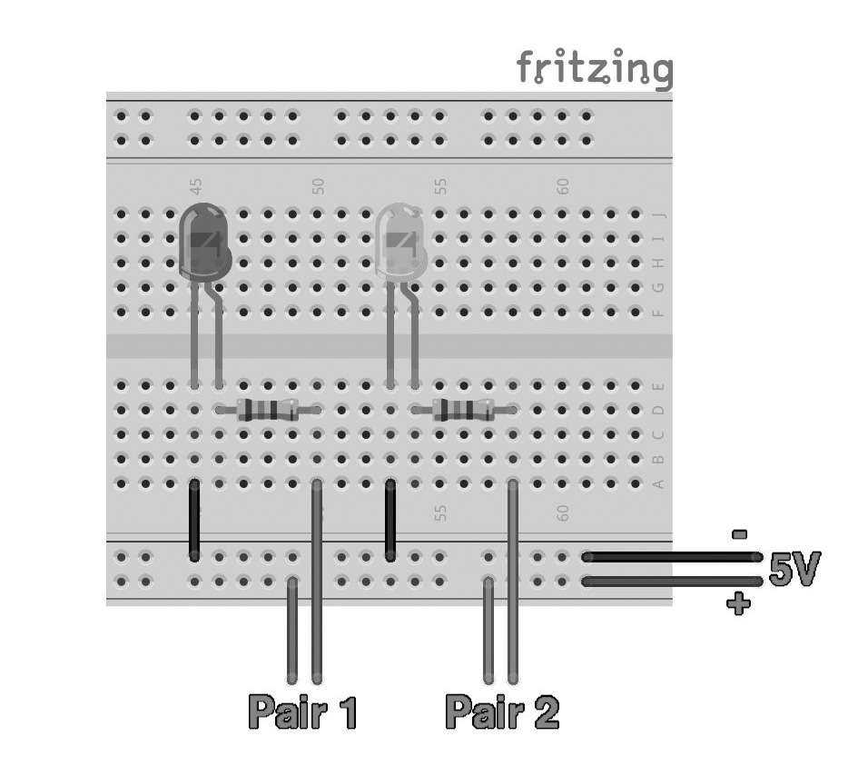
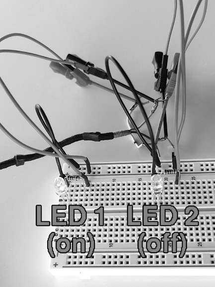
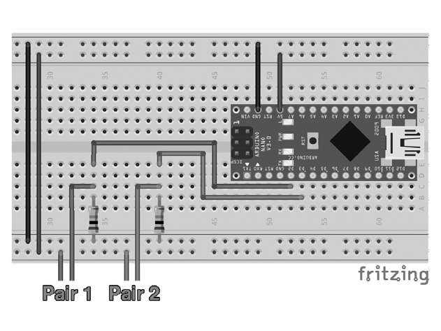
By arranging two LEDs, two resistors (150 ohms), and a few wires on a breadboard according to the two pictures below, I was able to visualize what was happening when the dial was turned:
As long as the dial remained in its resting position, one LED lighted up (let's call this one LED 1, attached to Pair 1, forming Switch 1) and one LED was off (LED 2/Pair 2/Switch 2). But the real magic started when the dial was rotated.
Upon turning the dial by approximately two numbers, LED 2 suddenly lighted up as well. Both LEDs kept lighting until the finger stop was reached. Once it was released, the dial was spun back to its initial resting position. During this movement, LED 1 pulsed off several times. Shortly before the dial came to a rest, LED 2 turned off again.
The pulses of LED 1 were fired rather quickly, but when slowing down the backward spin with my finger, I could observe that the number of pulses magically coincided with the number chosen on the dial! For instance, if number "5" was dialed, then LED 1 would shortly turn off five times, six times if number "6" was dialed, and so on.
In other words, I had found one signal at Pair 2, indicating if the dial had been turned out of its resting position and another signal at Pair 1, revealing the number that had been dialed.
That's definitely enough for a leap into the 21st century.
Entering the Arduino
In virtually every Arduino tutorial, dealing with switches comes very shortly after blinking LEDs (i.e., the hardware version of "Hello World').
Therefore, I will not go into detail about how switches can be connected to a microcontroller... just look it up if in doubt!
I opted for connecting both pairs to separate I/O ports and for using external pull-down resistors.
The actual circuit in place is shown in these two images:
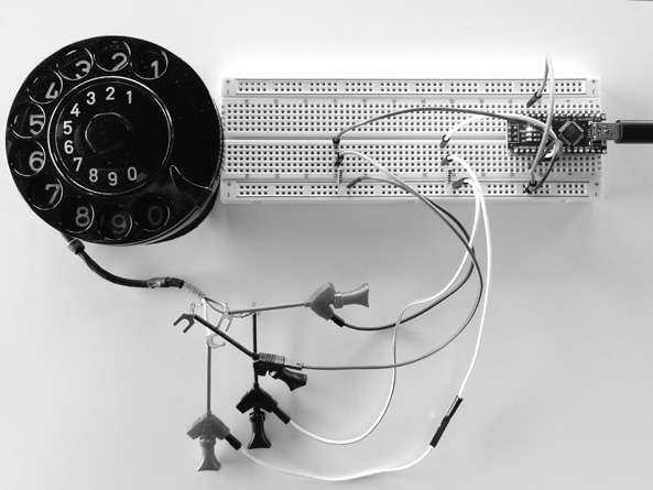
Besides the controller, it's just a bunch of jumper wires and two 10 kohm resistors. I used an Arduino Nano, but the below source code will work with most other Arduino flavors. The program logic is pretty straightforward: wait until Switch 2 closes (that's when the dial is being turned), then count how often Switch 1 shortly opens until Switch 2 opens again.
Sounds simple? It is!
Almost at least... if it weren't for an annoying phenomenon called bouncing which is caused by the mechanical nature of switches: they practically never turn on or off instantly, but instead exhibit a short period of "bouncing" back-and-forth between closed and open state. If not properly dealt with, this nuisance leads to a myriad of falsely detected switching operations. There are several rather complex approaches for debouncing using additional circuitry, but a microcontroller can handle this pretty well with some software adjustments.
A commonly proposed way of handling this within source code is allowing each switch to settle by introducing a short pause after each pulse is detected (i.e., "debouncing time").
In this application, especially debouncing time for Switch 1 is crucial. If set too high, pulses are missed (detected numbers are too small) and if set too low, too many pulses are detected (numbers too big). In case of my dial, the correct amount of pulses is reliably detected by waiting 65 ms. Optimal values for other dials may vary.
The listing below shows my implementation of the above. The code explains itself (of course, hi hi). Once your Arduino is wired properly on the breadboard and hooked up to your computer, you can upload the code via the Arduino IDE and then directly connect to its serial console by pressing Ctrl+Shift+M.
Once the dial is turned, the detected number should appear in the console window. If not, first check if the baud rate matches the value set in the program code before checking anything else.
And Next?
That's entirely up to you and your imagination!
Apart from push buttons, potentiometers, keypads, and a myriad of other sensors, you are now capable of integrating a very cool vintage input device into your next project! I'm sure you will come up with countless marvelous ideas. And even if you don't, you still have learned a thing or two about this fascinating piece of ancient electromechanical hardware that once helped in connecting the world.
Have fun!
/*
 * Setting up I/O pins for
 * - Switch 1 (normally closed/on)
 * - Switch 2 (normally open/off)
 *
 * There is only a limited set of I/O pins for each type of
 * Arduino that can be attached to an external interrupt.
 * Most (if not all) ATMega-based Arduino boards support
 * external interrupts on I/O pins 2 and 3.
 */

#define PIN_SWITCH1 2
#define PIN_SWITCH2 3

/*
 * Optimal debouncing times may vary be tween different dials.
 * The below values work best with _MY_ dial.
 *
 * -> Change SWITCH1 debouncing time if the number detected is
 *    not correct
 * -> Change SWITCH2 debouncing time if turning/reaching
 *    initial resting position is not detected properly
 */

#define SWITCH1_DEBOUNCING_MILLIS 65
#define SWITCH2_DEBOUNCING_MILLIS 100

/*
 * Global variables for exchanging values between interrupt calls, namely:
 * - debouncing buffers, storing when an interrupt routine was last called
 * - pulse count, incremented while the dial is turned
 */

volatile unsigned long switch1_debouncing_millis_last = 0;
volatile unsigned long switch2_debouncing_millis_last = 0;
volatile byte switch1_num_pulses = 0;

/*
 * Setup routine - putting everything into order
 */

void setup() {
	// Initialize serial and wait for port to open:
    Serial.begin(115200);
    while (!Serial) {/* just wait */}
    Serial.println("Serial ready.");
    Serial.print("Setting up pins...");
    pinMode(PIN_SWITCH1, INPUT);
    pinMode(PIN_SWITCH2, INPUT);
    Serial.println("done");
    Serial.print("Attaching interrupt...");
    //wait for closing of Switch 2 before doing anything else
    attachInterrupt(digitalPinToInterrupt(PIN_SWITCH2), isr_switch2_rising, RISING);
    Serial.println("done");
}

/*
 * Here goes the main program code... just in case you
 * want to do anything besides just detecting numbers
 */
void loop() {
}

/*
 * Interrupt routine, called when Switch 2 is closed.
 * It marks the beginning of dialling and replaces itself with the
 * interrupt routine waiting for Switch 2 to open again and
 * attaches the interrupt to Switch 1 in order to count the pulses
 */

void isr_switch2_rising() {
	long diff = millis() - switch2_debouncing_millis_last;
	diff = abs(diff);
	if (diff >= SWITCH2_DEBOUNCING_MILLIS) {
		Serial.print("turn of dial detected - counting pulses: [");
		switch1_num_pulses = 0;
		attachInterrupt(digitalPinToInterrupt(PIN_SWITCH1), isr_switch1_falling, FALLING);
		attachInterrupt(digitalPinToInterrupt(PIN_SWITCH2), isr_switch2_falling, FALLING);
		switch2_debouncing_millis_last = millis();
		switch1_debouncing_millis_last = millis();
}

/*
 * Interrupt routine, called when Switch 1 is opened
 * (marking a pulse). It is only active while
 * Switch 2 is closed and increments the global
 * variable "switch1_num_pulses"
 */

void isr_switch1_falling() {
	long diff = millis() - switch1_debouncing_millis_last;
	diff = abs(diff);
	if (diff >= SWITCH1_DEBOUNCING_MILLIS) {
		Serial.print(".");
		switch1_num_pulses++;
		switch1_debouncing_millis_last = millis();
    }
}

/*
 * Interrupt routine, called when Switch1 is opened.
 * It marks the end of dialling and:
 * - prints the detected number of pulses to the serial console
 * - detaches the interrupt routine from Switch1
 * - replaces itself with the interrupt routine waiting for Switch 2
 *   to close again and could be your starting point if you intend to do
 *   anything beyond simple numeral detection and output to the serial
 *   console.
 */

void isr_switch2_falling() {
	long diff = millis() - switch2_debouncing_millis_last;
	diff = abs(diff);
	if (diff >= SWITCH2_DEBOUNCING_MILLIS) {
		// do something with the detected number...
		Serial.print("]");
	for (byte b = 0; b < (11-switch1_num_pulses); b++)
		Serial.print(" ");
		Serial.print(" detected");
		Serial.print(switch1_num_pulses);
	 	Serial.print(" pulse");
		Serial.println((switch1_num_pulses != 1 ? "s" : ""));
		switch2_debouncing_millis_last = millis();
		detachInterrupt(digitalPinToInterrupt(PIN_SWITCH1));
		attachInterrupt(digitalPinToInterrupt(PIN_ SWITCH2), isr_switch2_rising, RISING);
		switch2_debouncing_millis_last = millis();
	}
}
|
Code: hacking-rotary-dials.ino