Citizen Engineer
Demystifying and Designing for USB-C
by ladyada@alum.mit.edu and fill@2600.com
If you're like us and have been creating or working with computers over the decades, you have a box somewhere in your home with adapters of all sorts.
Null modem cables, VGA gender changers, DVI-to-HDMI converters. The medium-low protocols like ADB, PS/2, parallel, and serial all got merged into the Universal Serial Bus (USB) standard.
Starting with version 1.0 that was for mice and keyboards, it was then expanded up to v2.0 for disk drives and cameras. Engineers at this point bumped up against some physical properties of USB - it was only two data pins and power maxed out at 5V 1A (technically, you weren't supposed to draw more than 0.5A, but most folks ignored that recommendation).
At that point, disk drives, video cameras, and networking devices needed faster data transfer and more power. So USB v3.0 came out with really unusual connectors that extended the data and power capability. This is when everyone making devices threw up their hands and said, Look, we've got all this technical debt that we've built up over the years - too slow, confusing connectors, low power, OTG incompatibilities, weird mutant connectors... Let's try to design something to one standard connector that you can't connect wrong."
They... sorta... succeeded. But, there's still plenty of gotchas that are literally hidden inside the cable! Now with USB-C, the cable always plugs in, both ends are identical and reversible, but there are at least six different types of USB-C cables. Designing electronics for USB-C is a lot more complex than the classic USB with only four pins, all well defined.
All USB-C connectors use a standard 24-pin oval connector. Four are ground, four are power, there are the classic USB data connector pairs D+/D-, as well as four more differential data pairs (five data pairs total), and then four more pins for configuration and non-data-sideband usage.
Since there's still millions of computers with classic USB connectors, the USB-C standard is a simple super-set that an be used for USB by only connecting the power/ground/D+/D- wires. If you have USB 3.x, those pins can also be connected to the USB-C with a mechanical adapter.
Thanks to the four sets of power pins and four extra differential pairs, USB-C cables can handle high-power/current and high-data transfer uses such as device charging, monitor/laptop power, up to 40 Gbps data (a.k.a., Thunderbolt 3), or any audio/video standards like HDMI/DisplayPort/Mobile High-Def.
For power usage, cables can carry 20V @ 3A and, in some cases, 20V @ 5A.
But... that's just what USB-C is specified to support. Whether you can actually use a USB-C cable for these purposes depends a lot on who made the cable and how much you're willing to spend. After all, to carry 100W you need a lot of thick copper to avoid voltage drops. To carry 4K DisplayPort, you need all those extra wire pairs. That means more soldering and more cost. Most people who want to connect their keyboard or charge their smartwatch don't need 100W and 40 Gbps and they don't want to spend $10 per cable. So a lot of cables skimp on the copper and wires, and that is where a lot of the confusion with USB-C comes in.
If you're using USB-C to replace your classic USB A/B devices, you'll only need USB v2.0 compatibility at 480 Mbps (nearly any cable and length up to four meters can handle that). As you move up to USB v3.0 / v3.1 Gen1 (5 Gbps), the max length goes down to two meters. At 3.1 Gen 2 (10 Gbps) and v3.2 SuperSpeed+ (20 Gbps), you will need to make sure your cable is designed for that purpose and it won't be able to go farther than one meter.
Alternative modes are protocols that are different than USB, but can use some specific USB-C cables that, again, are designed to handle the high data rates. Those modes cover Thunderbolt 3, DisplayPort, HDMI, MHL, and VirtualLink (as well as whatever we come up with next).
For example, Thunderbolt 3 cables that are longer than 0.5 meters need to be "active," which means they have electronics inside to amplify/equalize the signal for extended length cables or to perform protocol conversion. If the cable is 0.5 meters, it's called passive.
If you're connecting to a monitor, use a cable that is marked for use with DisplayPort. If you need 100W to power your laptop, do not use a 3A USB-C cable when you need a 5A one. How would you know what capabilities your cable has?
Well, USB-C cables are required to contain a power e-mark chip programmed to identify the cable and its capability. However, e-mark chips cost money, and people don't know what e-mark is. So if they can save $1 on a cable, they buy the one without. The effect of all these different cables, without chips, and perhaps even mis-marketed, is people who have been conditioned for decades to believe that connector shape dictates functionality. They are getting confused because cables that fit don't work and there's no way to know why.
So now you know what to watch out for with cables.
What if you are designing hardware to work with USB-C? Compared to classic USB, UBS-C's specification is a juggernaut, hundreds of pages long. If you're just trying to update your design to allow USB v1.x/v2.x compatibility, it's not too hard:
- Connect the four V+ pins together and the four GND pins together, and that's your 5V supply.
- D+ and D- are just like you remember, but don't forget to connect both D+'s and D-'s together so the cable is reversible.
- Connect a 5.1 kΩ resistor to ground from each of the CC1 and CC2 pins.
That's it!
The 5.1 kΩ resistors signal to the power delivery chip that you'd like 5V and up to 1.5A of current (assuming the port can supply 1.5A). If you need to determine how much current the power delivery can supply, you can measure the CC1/2 pin voltage before the pull-down - the pull-up on the other side of the cable can be calculated - 10 kΩ pull-up means up to 3A, 22 kΩ means 1.5A, and 56 kΩ is 0.5/0.9A max at 5V.
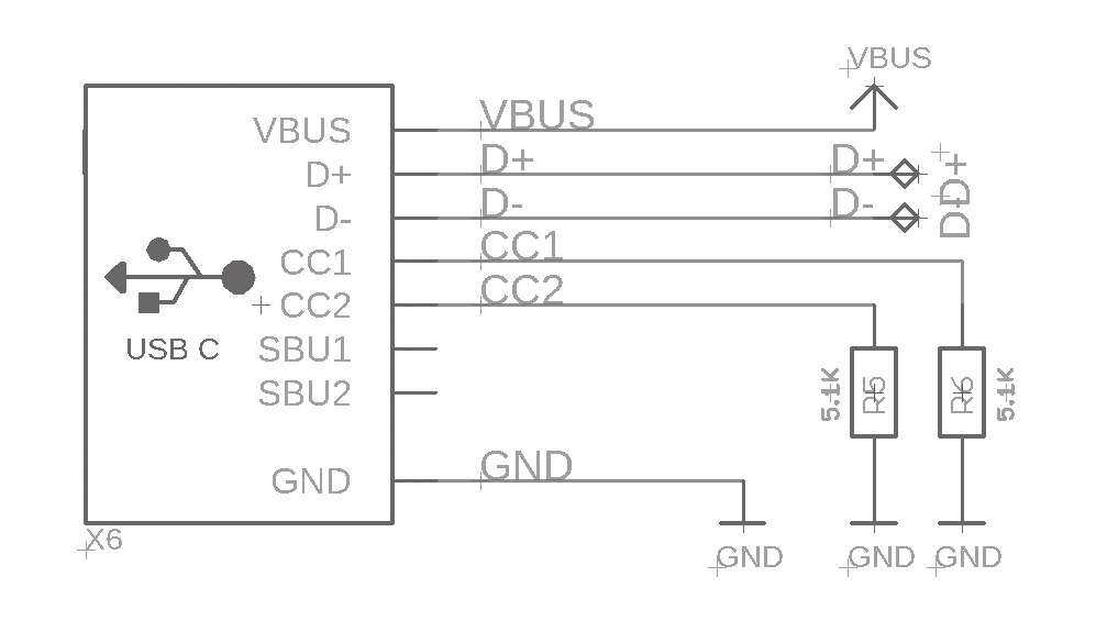
So for basic usage, there's no additional silicon required, just some small resistors, which makes updating designs easy.
Want more than 5V? Or have a design that can act as either host or device?
That gets a little more complex, but you can add a Power Delivery (PD) negotiation chip that will request higher voltages and currents, or manage sourcing or requesting power depending on what role you are playing in the connection. The BOM cost rises here, but is offset by being able to take part in the wide offerings of USB-C power supplies. And it isn't much more expensive than the original engineering solution where everyone used barrel jacks plus diode plus regulator to protect against plugging a 12V supply into a 5V device, or one with negative polarity. PD chips can be strapped with resistors or I2C programmable.
This isn't easy to get right: first-generation Raspberry Pi 4 computers didn't have those two CC resistors. Instead, only one was placed, which meant that some smart power delivery chargers would not work to power the Pi 4. Nintendo Switch also doesn't have PD spec compatibility. Only official chargers/cables are recommended, although without schematics it's hard to know exactly what went wrong.
Despite these hiccups, we like USB-C, especially for low-cost/power/data devices.
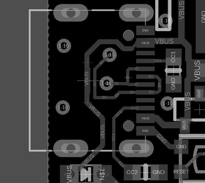
It's back-compatible enough and the connectors are great - strong, easy to manufacture with, not too large but easy to use. In most cases, you can get away with low-cost simplified USB-C connectors that have only one row of pins. They're about 25 cents each and not much larger than an USB micro B.
We'll be using USB-C for all our new hardware designs, and we recommend you do too!
Good night and good luck.