Arduino-Based Burglary Zone Input Tester
by Cezary Jaronczyk
An experimental design for testing hardwired-connected sensors.
Commercial burglary alarm systems protect many important facilities that are important for the safe operation of energy, water, transport systems, and so on. Among the safest security systems are those where the sensors are wired to the input circuits of the alarm systems or the zone loop inputs. However, if we perform a successful attack blocking the sensor using the device described here, it may tum out that the certified burglary alarm systems previously considered to be fulfilling their security functions should not be considered as such anymore and for the safety of the protected facility should be supplemented with security, solutions against the presented attack.
Compromising Hardwired-Connections
As the hardware zone loop is powered by a constant voltage level delivered by the burglary control unit or a zone expander, it is very easy to build and to apply devices that can read and remember the voltage level in the zone loop and later, on a request, feed it back to the zone loop.
When, for example, the applied compromising voltage level represents the status of "closed door" (window or other barriers), then opening the door (window or other barriers) will not affect the zone loop voltage level because a burglary control unit sees the zone loop status as not changed. In this way, someone can access a protected area without being noticed.
In the case where more than two wires count in a zone loop, more compromising devices may be used to connect to the wires in a circular pattern, in order to monitor and then substitute all voltages presented in the zone's loop circuits.
Figure 1 presents a full schematic of a device that can be used to compromise a burglary alarm system with a wired zone loop powered by a constant voltage level. If the zone input is compromised successfully, opening the door or window with a contact switch as a sensor makes the burglary alarm think that door or window is still closed. If this burglary alarm is certified, the certification probably did not meet all the burglary alarm standards' requirements regarding input circuits.
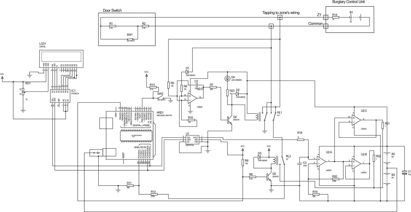
Figure 1
After connecting to the zone wires (tapping connectors to zone loop wires), the circuit first checks for connection's polarity. This is done by sub-circuits with operational amplifier U2D, with resistors R10, R5 , R6, diode D1, and capacitor C2. If the measured voltage on R10 is negative, it will automatically reverse input by drawing transistor Q2 and switched relay RL1 and D4 as LED lights ON.
If someone wants to bypass these sub-circuits, they need to measure polarity or modify circuits to measure the positive or negative polarity and tap properly to the zone input's wires. The sub-circuits R12 and R11 measure an actual zone input voltage through the relay contacts of RL1 and RL2. Relay RL2 will switch when we decide to change status from reading a zone loop voltage to attacking a zone loop input of the burglary alarm system.
The LCD1 display will print the measured voltage level of a zone loop. It receives measure data through the I2C's communication from the Arduino Uno microcontroller. This sub-circuit may be omitted, however. Wait a few seconds allowing measuring of the zone loop voltage level before switching to attack mode. The voltage input/output divider (R11 / R11 + R12) was set for ratio 1:4 for AD input voltage level requirements.
When a SW2 switch is on, the Arduino Uno supplies voltage at a level as was measured to the zone loop wires through the D/A interface based on MCP4725 interface and the amplifiers. The amplifier U2A with resistors R19 and R20 amplifies input four times and supplies it to the buffering amplifiers U2B and U2C (outputs connected in parallel) with an output voltage level that equals what's measured on a zone loop. This voltage is now presented on a zone loop, and switching SW1 (sensor) should not change the zone input voltage level of a burglary unit. In most cases, the attack should have a success rate of 90 percent in the modem burglary alarm systems.
Switch SW1 simulates a door contact open/close status if someone wants to play with circuits in a circuit simulation program. Do not forget to add a grounding referenced resistor, as the device itself presets the floating type voltage source.
LCD1 and IC1 are sub-circuits of LiquidCrystal_I2C LCD Arduino sketch (Model: YWRobot Arduino LCM1602 IIC V1).
Programming was done as easily as possible for a "dumb programmer as myself."
The code for Arduino is presented below:
The codes for a LiquidCrystal_I2C LCD display and DAC were found on the Internet. Delays of 200 were used for relay to stabilize, 500 for LCD display, and 20000 for compromising timing limits and can be changed as required.
Loaded Libraries:
NewLiquidCrystal
// or LiquidCrystal
Wire

/*
Configuration bytes:
// 12-bit device values from 0-4095
// page 18-19 spec sheet
buffer[0] = 0b01000000; // control byte
// bits 7-5; 010 write DAC; 011 write DAC and EEPROM
// bits 4-3 unused
// bit 0 unused
buffer[1] = 0b00000000; //HIGH data
// bits 7-0 D11-D4
buffer[2] = 0b00000000; // LOW data
// bits 7-4 D3-D0
// bits 3-0 unused
*/

#include <Wire.h> // specify use of Wire.h library
#define MCP4725 0x60 // MCP4725 base address
byte buffer[3];
unsigned int val;
#include <FastIO.h>
#include <I2CIO.h>
#include <LCD.h>
#include <LiquidCrystal_I2C.h>
LiquidCrystal_I2C lcd(0x27, 2, 1, 0, 4, 5, 6, 7, 3, POSITIVE); // Setup LCD
//LiquidCrystal_I2C lcd(0x27,16,2) LCD address may be different as to a LCD vendor specification

void setup() {
	pinMode(4, INPUT); // pin to starts measurement
	pinMode(13, OUTPUT); // Relay swith ON to start compromising
	pinMode(A0, INPUT); // pin as Analog IN to measure zone loop voltage
} // end setup

void loop() {
	int u = 0;
	int val = 0;
	buffer[0] = 0b01000000; // control byte
	delay(200); //Wait
	u = analogRead(0);
	val = u * 4; // read pot
	buffer[1] = val >> 4; // MSB 11-4 shift right 4 places
	buffer[2] = val << 4; // LSB 3-0 shift left 4 places
	float sensorValue = 0;
	sensorValue = u  *(5.0/1023.0) * 4;
	Wire.begin(); // begin I2C
	lcd.begin(16,2);
	lcd.backlight();
	lcd.setCursor(0, 0);
	lcd.print("Measured Volts =");
	lcd.setCursor(0, 1);
	lcd.print(sensorValue);
	lcd.print("__");
	lcd.print(u);
	delay(500);

	while (digitalRead(4) == LOW) {
		//digitalWrite(2, HIGH); // ready LED ON, option
		delay(200); // delay for conats to sabilize
		Wire.beginTransmission(MCP4725); // address device
		Wire.write(buffer[0]); // pointer
		Wire.write(buffer[1]); // 8 MSB
 		Wire.write(buffer[2]); // 4 LSB
 		Wire.endTransmission();
 		delay(200); //Wait
 		digitalWrite(13, HIGH); //Relay 2 ON to compromise burglary zoneloop
 		delay(20000); //Wait
 	}
} // end loop
|