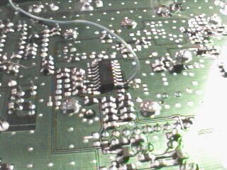
5. Tapping the Discriminator: Get yourself a short length
of thin wire. In this example, I used a strand of CAT5 cabling that was
lying around. Solder it to the correct pin. In this case (and many other
scanners), the pin is #9. If you're unsure, refer to Bill Cheek's SCANDATA.TXT
file for reference.
Got it! Make sure your hands are steady on this one -
don't screw up any of those surface-mounted resistors or anything.
6. Get yourself a drill. The bit size should be around
15/64 of an inch. Drill a hole into the back of the radio, right where
the serial number is. Be careful not to drill through the board or speaker!
Attaching the jack should be a snap. Solder a single wire to the jack's
ground terminal. Then, solder the NEGATIVE terminal of that electrolytic
capacitor to the center conductor of the jack. 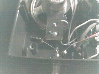
Slide the board back into the radio's casing, and attach the discriminator wire to the positive terminal of the capacitor. Tape everything up to prevent shorts or other nasties.
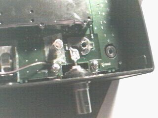
7. Screw the board back into the casing. Grab the wire
that you soldered to the jack's ground terminal, and solder the other end
to a convenient ground point. One of the screws holding the board down,
by the antenna terminal, is a decent choice.
8. Now, resolder the antenna terminal to its input, just
like it was before you opened it up. Be liberal with the solder. Reattach
all of the molex connectors, and resolder the backlight connections. Put
the case back on. It should look something like this:
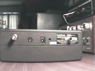
This photo isn't that great, but you can see the discriminator jack right where the serial number is. You're done! Attach the power connector, antenna, and a suitable cable for your new discriminator output, and you are in business.
For kicks, here's what a signal will look like out of
your discriminator and onto a oscilloscope:
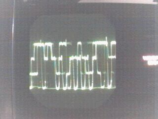
See how straight the lines (traces) are? That's because
you now have a clean (flat) audio output. Try that with the speaker jack...
it will look nothing like this.